AC Motors and Drives Fundamentals

AC Motors and Drives Fundamentals
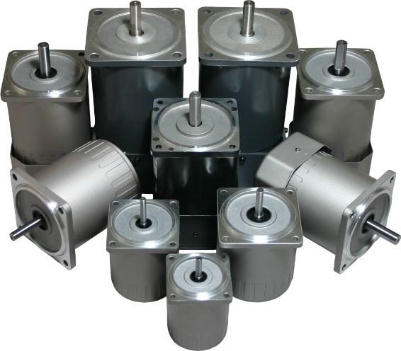
General AC Motor Characteristics
AC motors are designed to run at constant speed. This speed is determined by the applied frequency of the AC current, and the number of poles wound into the motor. A pole is a winding on the stationary part of the motor (the stator) which becomes magnetized when current is supplied, creating a north and south pole within the stator. This causes the rotor (the inner part of the motor, which is also magnetized) to spin as the magnetic fields interact. Common configurations in industrial motors are 2-pole (one set of north and south), 4-pole, 6-pole and 8-pole.
AC motor speed can be calculated thus:
RPM = (120 x Frequency)/Number of poles
Example for a 2-pole motor:
(120x60)/2 =3600RPM
Similarly, a 4-pole motor would be 1800RPM, a 6-pole motor would be 1200RPM, and an 8-pole motor would be 900RPM. However, if you look at a motor nameplate, these numbers will not appear. This is due to some electrical losses known as slip. Most motors have 3% to 5% slip. This would show up on the labels as:
2-Pole: 3450RPM
4-Pole: 1725RPM
6-Pole: 1140RPM
8-Pole: 850RPM
These numbers on the nameplate, or label, are referred to as rated speed or base speed. Again, supplying the required voltage at 60 hertz will have the motor running at these speeds. Starting an AC motor in this way will cause the motor to instantly attempt to run at full speed and draw as much current as needed to accelerate the motor. This is referred to as “across the line” starting and offers no control of acceleration or limiting the current.
Basic AC Drive Function
The AC drive addresses all these characteristics of AC Motors, and also causes the motor to run at variable speeds. The AC drive is microprocessor-based, supplies controlled acceleration, and limits the current to the motor, protecting it from burning out. In simplest terms, it accomplishes this by controlling and varying the frequency to the motor, delivering the current and voltage to the motor with high-frequency switching of the windings. Remember, the speed is proportional to the applied frequency. Therefore, AC drives are referred to as variable frequency drives or VFDs.
AC Motor Selection
VFDs by design only control three-phase motors, so any motor selected must be three-phase. Most manufacturers of VFDs do not manufacture motors and vice versa. As such, if there is not a recommended matched system, care must be taken to select the correct motor. There is certain nomenclature that one needs to be aware of.
Induction motors are standard AC motors you might see on a pump or fan. These are not designed to run on VFDs. These can be run on a variable frequency drive, but with severe limitations. The speed reduction can only be 2 or 3:1, meaning the best you can do is 600 or 900 to 1800RPM speed range. Continuous use below this can cause excessive heat, since induction motors are not designed to withstand the high switching.
Inverter-Rated motors are typically of newer design and higher efficiency, and can withstand the switching better that the standard induction motor. Speed range is a little better (10:1) yielding 180-1800RPM.
Inverter duty motors have windings specifically wound to withstand the switching of the VFD. Speed range on these would be 1000:1.
Closed-loop vector motors are inverter duty motors with encoders mounted on them to give better speed control and eliminate speed fluctuations.
Drive Modes
AC drives can be set up to run in various control modes. The two primary control modes are constant torque and variable torque. As the name implies, constant torque mode supplies the same torque regardless of speed. Typical applications are hoists and conveyors. In variable torque applications, the load changes with velocity. Typical applications include fans and centrifugal pumps.
Within these modes, there are 3 options: Volts per hertz, open loop vector and closed loop vector.
Volts per hertz (abbreviated v/Hz) is open loop (no feedback) and operates on the principle of varying the voltage and frequency to the motor to get variable speed. The motor can experience speed variations based on external forces like increased friction on the system. Open loop vector operates the same as v/Hz, but also utilizes the characteristic that a rotating motor will generate an electric force in the opposite direction of the input. This force is referred to as back EMF. In addition to supplying the voltage and frequency to the motor, the open loop vector drive monitors this value and adjusts if the motor is trying to go too fast or slow. The result of this is less speed variation. As opposed to open loop vector, closed loop uses velocity feedback from an encoder. Unlike the analog feedback from the motor, the encoder is digital and attached to the motor, so it yields more accurate information on the motor velocity. This gives much better speed regulation when constant speed control is essential.
AC Drive Selection
Drives are selected based on horsepower, voltage input and environmental constraints. Once you have determined the horsepower requirement, you can select the drive that meets your available input voltage. Drives are available with 115V, 230V 1PH, 230V 3PH and 460V 3PH. From the discussion earlier, the motors need to be three phase. All VFDs regardless of input, output 3 phase to the motor. The 115V units have internal double circuitry and convert the output to 3-phase. These are usually only available to 1½ HP. Drives with input of 230V 1PH are available through 5HP. Drives with 230V or 460V 3PH input go much higher in horsepower. Our offering at Anaheim Automation is currently limited to 30HP.

In terms of environment, the choice of configurations is chassis, NEMA 1, NEMA 12, NEMA 4, and NEMA 4X. In all these configurations, the internal components and functions are the same.
Chassis configurations are open frame with the electronics exposed to the outside. These are intended to mount in a customer enclosure. This is a space-saving design if multiple drives are in your system.
NEMA 1 drives are enclosed to add protection to the electronics. However, these enclosures have vents, so there is no protection from liquids or dust.
NEMA 12 units are enclosed with no vents and have seals to protect dust, falling dirt and splashing or dripping liquids from entering the drive. Designed for use indoors.
NEMA 4 is similar to NEMA 12, but the gasketing is enhanced to protect against water from a hose directly on the enclosure. Can be used indoors or outdoors.
NEMA 4X meets all the criteria of NEMA 4, but is also corrosion-resistant. These enclosures are typically stainless steel or polycarbonate.
Additional Information
For more information on AC Motors and Drives, please see our AC Motor Guide.
Featured VFD Series:
.png)
- Input Voltage: Single-Phase, 100-120V
- Rated Power: 200-750 Watts (0.25 - 1 HP)
- Great for normal duty and soft-start operation
- Control Mode: V/F control; Open-loop vector control
- Auto torque boost and auto slip compensation function
- Built-in PID control
- Modbus Communication (RS485 baud rate up to 4800-19200bps)
- Sleep/wake up function
- Input Voltage: Single-Phase, 200-240V
- Rated Power: 400-1500 Watts (0.5 - 2.0 HP)
- Great for normal duty and soft-start operation
- Control Mode: V/F control; Open-loop vector control
- Carrier frequency up to 15KHz
- Auto torque boost and auto slip compensation function
- Built-in PID control
- Modbus Communication (RS485 baud rate up to 19200bps)
- Sleep/wake up function
.png)
- Input Voltage: Single-Phase, 200-240V
- Rated Power: 400-2200 Watts (0.53-3.0 HP)
- Frequency from 0-300Hz
- Control Methods: V/F control, Sensorless Flux Vector Control, Closed-Loop Vector Control
- Built-in EMI Filter and Brake Resistor
- Modbus RTU or ASCII Protocol (RS485 baud rate up to 125000bps)
- Supports Analog or Discrete Input Control, Communication Control, or Panel Control with Detachable Remote
.png)
- Input Voltage: Three-Phase, 200-240V
- Rated Power: 0.4-22 kW (0.53-30.0 HP)
- Frequency from 0-300Hz
- Control Methods: V/F control, Sensorless Flux Vector Control, Closed-Loop Vector Control
- Built-in EMI Filter and Brake Resistor
- Modbus RTU or ASCII Protocol (RS485 baud rate up to 125000bps)
- Supports Analog or Discrete Input Control, Communication Control, or Panel Control with Detachable Remote